The methods described on this page start by simply drawing lines of various shapes and end with a powerful suite of techniques to create photo-realistic Procedural Textures.
Don't underestimate even the simples methods: they are capable of great things!
Interpolation is a method of filling in missing information and can consequently be incredibly complex, but fortunately the simplest methods are extremely useful.
The simplest beginning builds on the methods used for mapping from one scale to another as discussed on the Mapping page.
Simply join two known points with a straight line and work out the missing values using equations based on straight-line graphs.
|
If all that is known in this graph is the position of the red points, it is simple and fast to join them with straight lines and for many applications this is good enough.
Creating the smooth blue curve between points is what splines are used for (a Spline is a bendy ruler that draughtsmen used to use) but there is a lot that can be done simply by considering just two points at a time, so that is the beginning.
|
gFilters.h holds Interpolation methods from basic one dimensional curves, periodic shapes, steps and ramps to full image filters like lanczos, CatRom, CatStep, Mitchell.
Interpolating Gradient Fills
 A typical use for one dimensional interpolation is creating a grayscale gradient fill.
Imagine starting at the bottom left of a square and drawing a vertical black line; move to the right one pixel and draw the next vertical line, but what shade should it be?
Computer grey levels are BYTEs: integers in the range [0,255].
The square has a width in pixels that needs filling, so the pixel positions vary in the range [0,Width].
The examples later on are 100 pixels square, so the range will be [0,100].
A typical use for one dimensional interpolation is creating a grayscale gradient fill.
Imagine starting at the bottom left of a square and drawing a vertical black line; move to the right one pixel and draw the next vertical line, but what shade should it be?
Computer grey levels are BYTEs: integers in the range [0,255].
The square has a width in pixels that needs filling, so the pixel positions vary in the range [0,Width].
The examples later on are 100 pixels square, so the range will be [0,100].
As the pixels are iterated, a parameter, t, can be created with a range [0,1] using t=Pixel/Width; (making sure that it's not an integer divide).
Having found the parameter, it can be used to interpolate a grey shade in the range [0,255] using gFilters::Interpolate(t,0,255);
If you wanted to start with white and end with black you simply reverse the range to [255,0] using gFilters::Interpolate(t,255,0);
For the [0,255] version, though, and indeed any ranges that start from zero, it is obvious that all that is needed is to multiply the parameter t by 255:
for(WORD x=GetWidth(); x--; ) {
double t=double(x)/GetWidth();
BYTE B=BYTE(Round(255*t));
for(WORD y=GetHeight(); y--;) SetPixel(x,y, RGB(B,B,B));
}
GetWidth(), GetHeight() and SetPixel are members of CPixelBlock which was used as a base class.
Round is declared in Global.h and should be used instead of casting from floating point to integer in tight loops because the standard casts clear the processor pipeline which stops caching working and slows things down a lot.
For a White to Black gradient, the following code could be used:
for(WORD x=GetWidth(); x--; ) {
  double t=double(x)/GetWidth();
  BYTE B=BYTE(Round(gFilters::Interpolate(t, 255,0)));
  for(WORD y=GetHeight(); y--;) SetPixel(x,y, RGB(B,B,B));
}
 gFilters contains methods which will alter the shape of the line in the middle without moving its ends which allows you to have more white, or more black.
The gradient on the left used the cosine filter:
gFilters contains methods which will alter the shape of the line in the middle without moving its ends which allows you to have more white, or more black.
The gradient on the left used the cosine filter:
for(WORD x=GetWidth(); x--; ) {
  double t=double(x)/GetWidth();
  BYTE B=BYTE(Round(gFilters::InterpolateCosine(t, 0,255)));
  for(WORD y=GetHeight(); y--;) SetPixel(x,y, RGB(B,B,B));
}
These are gFilter's Curve functions which simply alter the parameter, t:
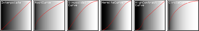
Each of these 'greyscale gradient fills' change from black to white using different gradients (joining lines) which are not necessarily straight.
I've used a red line as a cross-section on each gradient: when the line is at the bottom, the colour is black, and at the top, white.
You can see the shape of the colour-change from the shape of the red line.
The first gradient varies linearly (using the Interpolate method): black at the left (the red line is at the bottom) and white at the top (red line at the top).
The gradient looks evenly spread (subject to the 'Gamma Correction' that your screen may or may not have).
The second gradient varies using the square root function. Most of the change in brighness happens at the black end, and the right hand side is white for longer.
The third gradient varies using the first part of a sine wave; it's similar to the Linear version to start with but gets white earlier and is brighter overall.
The fourth uses a cubic polynomial and gives gentle changes from the end points.
The fifth is using a fairly complicated high-contrast filter changing from a sweeping curve to a linear finish.
The final image shows a circular curve: the shading get white very quickly.
You can see the maths involved in gFilters.h, there are no huge equations, but for most people, using the methods is more interesting than understanding them!
They are enormously useful tools as you can see in the Procedural Textures page.
Adjustable gradients
So what happens if the shape you need is a little different from any of those?
There are two methods which help called Bias and Gain.
Each of them alter the parameter that you provide in a predictable way.
This is best understood by starting with a straight line and applying a Bias to it, but you can feed any shape in to bend it.
You have your parameter, t, varying from 0 to 1 and give it to the Bias method to change.
You define the strength of the effect with another parameter which also varies between 0 and 1.
Small values of Bias pull the result towards the x axis, and large towards the y axis.
Gain is simply two Biases, one before the mid-point and one after.
so the mid-point doesn't move, the low end moves as if a simple Bias was used and the high half does the opposite.
This looks like twisting the mid-section to be more horizontal for low Gain and more vertical for high Gain.
A Bias or Gain value of 0.5 have no effect.
Normally, it would be wise to have such a function use a Signed Interval [-1,1] for the Bias and Gain values which would make zero normal and clearly indicate the direction with the sign of the parameter
but these methods are based on natural logarithms which don't like negatives and are slow enough without doing our own Signed(...) conversions!
This is the code I used to draw these images.
for(WORD x=GetWidth(); x--; ) {
  double t=double(x)/GetWidth();
  t=gFilters::Bias(t, 0.75);
  BYTE B=BYTE(255*t);
  for(WORD y=GetHeight(); y--;) SetPixel(x,y, RGB(B,B,B));
  SetPixel(x, WORD(Round(gFilters::InterpolateLinear(t,GetHeight(),0))), 0xFF0000);
}
Adjustable End Points
There are several methods that take extra parameters to define when the parameter, t, should start and stop having an effect.
The simplest is a switch point: Step(t,a); you provide t and another number, perhaps 0.3, and if t is lower than 0.3 the result is zero, and once t has become larger than 0.3, the result is one.
The interesting thing about these methods is that they don't need to work on t, they can work on actual values, but the return values are always in the range [0,1], so that last example could be Step(x,30); and the return value can be used as the parameter, t.
The other step methods all take three parameters (x,a,b) and expect x to vary through the two other values; the returned parameter is in the range [0,1].
0 means that x was before a, and 1 means that x was after b.
The simplest is a straight-line Ramp, the most useful is a cubic sine-shaped (but far faster) one called HermiteStep.
The ranges of the input parameters are unspecified, so there are two ways to use HermiteStep here; it can work on the parameter, t:
for(WORD x=GetWidth(); x--; ) {
  double t=double(x)/GetWidth();
  t=gFilters::HermiteStep(t, 0.1,0.9);
  BYTE B=BYTE(Round(255*t));
  for(WORD y=GetHeight(); y--;) SetPixel(x,y, RGB(B,B,B));
}
or it can work on the actual scale, x:
for(WORD x=GetWidth(); x--; ) {
  double t=gFilters::HermiteStep(x, 10,GetWidth()-10);
  BYTE B=BYTE(Round(255*t));
  for(WORD y=GetHeight(); y--;) SetPixel(x,y, RGB(B,B,B));
}
In the above code you can see that I've told the HermiteStep not to start stepping until it is 10% away from the sides.
This is what they look like:
These simple steps are fantastic for fast antialiasing and threshold clipping.
You can see a couple in use on the Colour Spline page, and a demonstration of thresholding on the Procedural Textures page:
That last image was made using gFilters::Ramp(t, 0.55, 0.75); Changing the numbers selects different slot sizes from the blurry source image.
If the gap between the numbers controls the level of antialiasing in the final image: a big gap makes blurry edges and decreasing the gap can end up with jaggies (the ramp becomes a step).
If the rate of change of the antialiasing needs to be smooth, use HermiteStep instead of Ramp.
Periodic Repeating and Mirroring
These are the periodic gradients (simply give x and a period (wavelength) to the method, and get a parameter in the range [0,1] out as usual).
Notice that the Triangle starts high at t=0: this what the algorithm naturally creates. To have a Triangle that starts at zero, use t=1-Triangle(x,Period) as used in the Repeat method:
static double Repeat(const double& x, const double& Count, bool Mirror=false) {return Mirror ? 1-Triangle(x,0.5/Count) : SawTooth(x,1/Count);}
The first image was created using t=CircleCurve(Repeat(t,2)); and the second image with mirroring set: t=CircleCurve(Repeat(t,2,true));
Mixing these functions together is the key principle of generating procedural textures.
Image Processing Filters
The last methods are image processing filters: designed to take a parameters in wider ranges (termed Filter Width).
Their return values may dip below zero (indicated with a horizontal grey line).